- Published on
PMT Counter
One of my recent projects led me to explore the fascinating world of the RP2040 microcontroller. As you can see from my bio I'm neither an electrical engineer nor an electronics expert. Still, I find electronics fun and love building things just for the thrill of it.
I still remember being amazed as a young teenager when I made an LED blink with a few wires and an Arduino board. Or blowing up the power supply of my desktop PC while trying to fix it. At the university curiosity led me to experiment with cloning RFID devices to get access to private parkings, though failing miserably... Still, the understanding of basic circuits came in handy a couple of times when fixing my old Fiat Punto or when assembling my first gaming PC.
Nevertheless, for a long time, designing PCBs felt out of reach. Something achievable only by real experts. But a few years ago, I realized how simple it is to design a PCB, how affordable it is to manufacture, and how fun it can be to debug. So, between physics projects, I started tinkering with KiCad, creating my first PCB prototypes for devices I needed in the lab.
Given how much of the modern world relies on electronic devices, I believe it's crucial to improve the public literacy of electronics. Whether you're in science, engineering, or even just curious about how things work, having a basic grasp of electronics can be incredibly empowering.
For these reasons, if you didn't try out some PCB designing, go ahead and download KiCad! It's available for Windows/Mac/Linux and you can find a lot of online tutorials on how to start.
But enough digression on how cool electronics is, this post is about my recent failures in it!
PMT Counter
I started designing this PCB board as I was in need of counting fast pulses coming from a PMT in our lab in Amsterdam. For people who, weirdly, never used a PMT in their life; a PMT is a device capable of detecting photons that hit its sensitive area (the photocathode). Each photon can generate an electrical signal, usually a TTL pulse, which can be easily read.
The efficiency of a PMT is called quantum efficiency, and, simply put, it indicates how many photons are required on average to generate a signal. A perfect PMT would have a quantum efficiency of 1 and produce one signal for each incoming photon.
You can imagine a PMT as a single pixel of your phone camera. Basically, it can detect light. Just a PMT can do this much more efficiently than your camera and at extreme wavelengths (eg ultra-violet or infra-red).
So, what do we use PMTs for? In our case, we use them to detect the internal states of trapped ions! Depending on their internal quantum state, ions can emit photons with a frequency of one each few nanoseconds. For this reason another characteristic of PMTs is their count rate capability which is usually in the hundreds of MHz.
For all these reasons I ended up designing a PCB board capable of counting TTL signals coming from a PMT. The board is capable of reaching a count rate of ~1.5 GHz although it was never tested at these speeds. Things become a bit fuzzy when signals reach frequencies of the order of GHz as their wavelength becomes comparable with the size of the board or its tracks. I tried the best to impedance match the whole board but (as I already pointed out) I ain't an electrical engineer and you should do some testing in case you would ever be interested in using it at these speeds.
You can find all the designs and a guideline of the PCB board here.
Dealing with PECL logic
Initially I imagine this way of solving my TTL counting necessities:
- Find an IC capable of counting TTL pulses up to 100MHz
- Connect a RP2040 to it
- Done
However, as I could not find any IC capable of counting TTL signals at that speed I got stuck at step 1. This brought to using the MC100EP016A a 8-Bit Synchronous Binary Counter with an operating frequency 1.3 GHz.
Where is the problem you might wonder? The MC100EP016A uses PECL logic while my signals are TTL like. Furthermore, the RP2040 uses LVTTL logic signals. As you might have already guessed, this brought me down the rabbit hole of digital logic conversion. What fun!
PECL
When dealing with high speed signals I ended up in the confusing world of PECL logic and its termination. What confused me for long was that some devices use a coupled logic ( and ) and some use just one signal (). It was not immediately clear how to properly terminate such signals and how to deal with their connection.
From an online search it appears that connecting single and dual pair PECL signals is tricky. More information about this can be found here and here.
In practice, to keep it short, the signals have to be terminated to using a resistor having the same impedance as the transmission line (usually ). The figure below illustrates the key points for most single/dual PECL connections:

I believe this figure makes it clear that connecting two different PECL ICs is not a trivial task and in the board I had to connect a single-pair PECL IC to a dual-pair PECL IC 🙄.
As the MC100LVELT23 (LVPECL to LVTTL) requires differential LVPECL inputs while the MC100EP016A (counter) is a single-ended IC, we are in need of generating a source. We could do this using a Thévenin equivalent circuit as shown in AND8020-D. In the first version of the board I naively followed this idea, noob mistake (but I'll leave this to the next section).
The MC100EP016A provides a bias voltage output. We can use that as a threshold voltage for PECL logic. Again, following AND8020-D , however, we should use the of MC100LVELT23 after current amplifying it. For these reasons the board uses an op-amp (OPA340) in voltage-following mode.
Note that there is a small discrepancy between the standard range defined as (or ) and the V of MC100EP016A. In this case the MC100LVELT23 is expecting a reference bias voltage of 2V however the MC100EP016A provides 1.875V (no idea why, as it's rated for V). Luckily the two are close enough and no further voltage translation is needed.
Thévenin equivalent
The first working version of the board used a Thévenin equivalent circuit to generate the bias voltage . While voltage regulators today are incredibly cheap and easy to use, I decided to go old school—what could go wrong, right? Well, nothing when you're connecting just two ICs.
But once you start using the bias voltage across multiple ICs, things get trickier.
As mentioned in AND8020-D, using a Thévenin equivalent termination does have its benefits, particularly in terms of being more robust against variations in . Table D1, provides the ideal resistances depending on and , calculated using Eqs. 14 and 15, ensuring the resistor network matches the characteristic impedance of the transmission line.
Specifically, the values are given by:
(141)
(151)
For V and V and 50 impedance traces one needs and .
But what happens if you have to terminate more ICs ()? As each receiver IC will have its own sub-circuit, Eqs. 14 and 15 are always satisfied. Nevertheless, from the point of view of the power supply in this case you will end up with parallel resistance network as and . The amount of current dissipated on the resistive network starts to increase as: . Although the LDO used on the board can handle these currents, I noticed some heat issues in this design. To address this, I switched to a dedicated LDO (MAX1735) for generating .
It is important to note that, since the termination voltage reference needs to sink current, the LDO chosen must be capable of current sinking. A current-sinking negative LDO, modified for positive operation, can do the job, as outlined here. The MAX1735 can sink up to 400mA. Since I wasn’t entirely sure how much current the MAX1735 would need to sink, I added an extra diode (D10 in the latest version) as a precaution.
Termination of GPIO and why is important to debug the debugger
I tested and debugged the first version of the board using a TTL frequency generator and comparing the number of counts in a batch with the expected number of counts from its frequency. All seemed working, I expected 24 counts and was getting 24, sometimes a 23, sometimes a 25 but, tbh, the frequency generator was probably as old as me.
What the PMT board returns is the list of counts in the last acquisition batch. Under typical testing conditions, I set my frequency generator to 18MHz frequency, ask the board to return 200 bins while clocking the RP2040 at 125MHz with a integration time of 50 instructions. As the counter would count the pulses in and the source frequency has a period of I was expecting counts per batch. And thats what I was getting, the PMT board would return me data such as:
[7, 7, 7, 7, 7, 7, 7, 7, 7, 7, 7, 7, 7, 7, 7, 7, 7, 7, ... , 7, 7]
All good. Slowing reducing the source frequency to let's say 12MHz would give me:
[4, 4, 4, 4,4, 4, 4, 4,4, 4, 4, 4,4, 4, 4, 4,4, 4, 4, ... , 4, 4]
Seems the board is working fine, all test passed, let's integrate it in our system.
Well... you might have already seen the problem here. I am testing the board in an unusual condition, where the pulses in a batch are always the same number, defined by the frequency of my frequency generator. When connecting the board to a source of randomly distributed pulses (as a PMT can be), I started seeing that something was off... I was getting data of this type:
[0, 0, 0, 0, 0, 0, 0, 0, 0, 0, 0, 0, 0, 0, 0, 0, 0, 0, ... , 0, 0]
[1, 1 ,1, 1 ,1, 1 ,1, 1 ,1, 1 ,1, 1 ,1, 1 ,1, 1 ,1, 1, ... , 1, 1]
[0, 0, 0, 0, 0, 0, 0, 0, 0, 0, 0, 0, 0, 0, 0, 0, 0, 0, ... , 0, 0]
[0, 0, 0, 0, 0, 0, 0, 0, 0, 0, 0, 0, 0, 0, 0, 0, 0, 0, ... , 0, 0]
[1, 1 ,1, 1 ,1, 1 ,1, 1 ,1, 1 ,1, 1 ,1, 1 ,1, 1 ,1, 1, ... , 1, 1]
[0, 0, 0, 0, 0, 0, 0, 0, 0, 0, 0, 0, 0, 0, 0, 0, 0, 0, ... , 0, 0]
Something's fishy here, in one acquisition cycle I was getting always 1 or 0 photon counts independently on the number of bins. I was expecting a Poissonian distribution:

But this statistic should appear inside each acquisition with mostly 0 counts and sometimes a 1. This is not what I was seeing! To make this even more mysterious, I was getting the right statistics when slowing the RP2040 clock down below 1MHz...
I immediately thought that something was off with the DMA and how I was accessing memory on the RP2040 at high speed. Perhaps the FIFO was saturating and new data was not getting written in memory. After spending a couple of days on this I decided to test the code removing the counter reset instruction. In this way I was expecting to read data as:
[2, 4, 6, 8, 10, 12, 14, 16, 18, 20, 22, 24, 26, ...]
Assuming around 2 counts per batch. Nevertheless what I was getting again was:
[2, 2, 2, 2, 2, 2, 2, 2, 2, 2, 2, 2, 2, 2, 2, 2, ...]
At this point everything was pointing to a DMA memory problem in my code OR the latch not being updated after each batch. After convincing myself (and here I want to thank people at the Technology center of the UvA) that my code was correct (to the point one can be sure of..) I decided to have a better look with the a logic analyzer.
Using an RP2040 with Sigrock PulseView, it's possible to probe up to 24 digital and 3 analog signals at 2.4 MHz. (I mention 2.4 MHz as I couldn't acquire data at higher rates—probably because I didn’t experiment enough with the software).
Connecting my probe (another RP2040 running Sigrock) to the GPIO of my board I started looking at what was happening on the data lines (first 8 pins) and the control whose Pins are defined as follows:
//Latch pins
#define OE 10 --> D12 of PulseView
#define LE 11 --> D13 of PulseView

//Counter pins
#define CE 12 --> D14 of PulseView
#define TLCD 13 --> D15 of PulseView
#define PE 14 --> D16 of PulseView
#define MR 15 --> D17 of PulseView
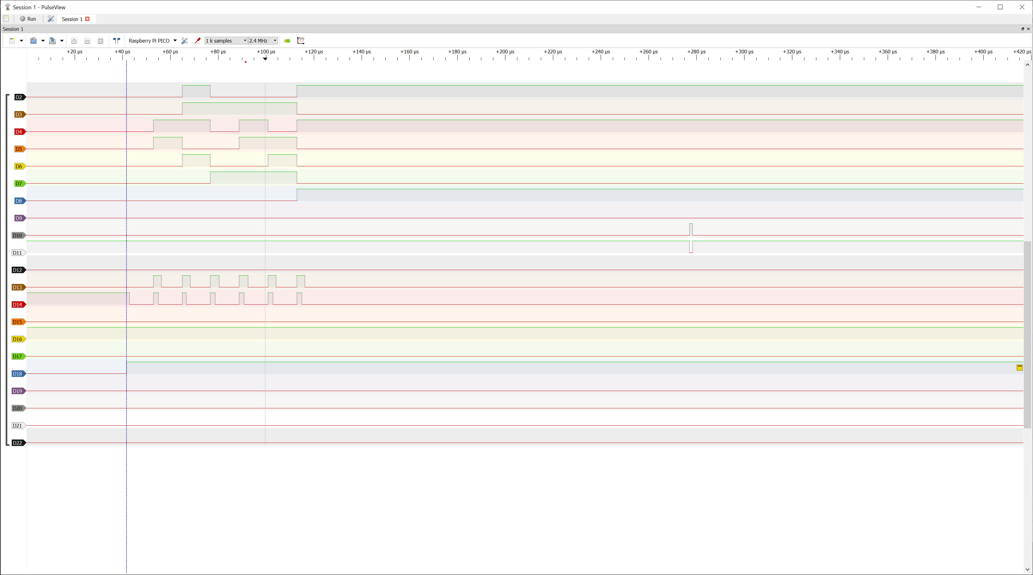
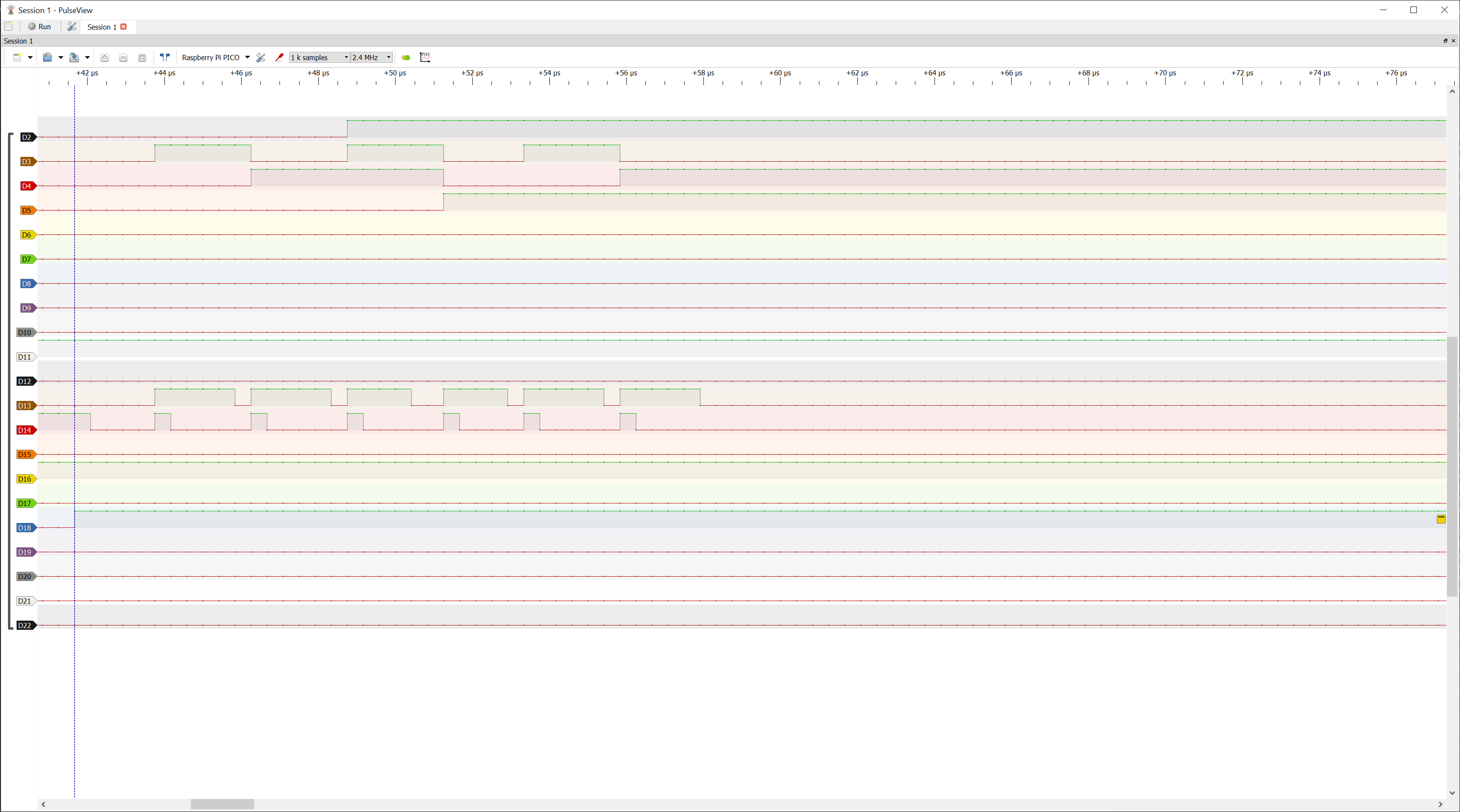
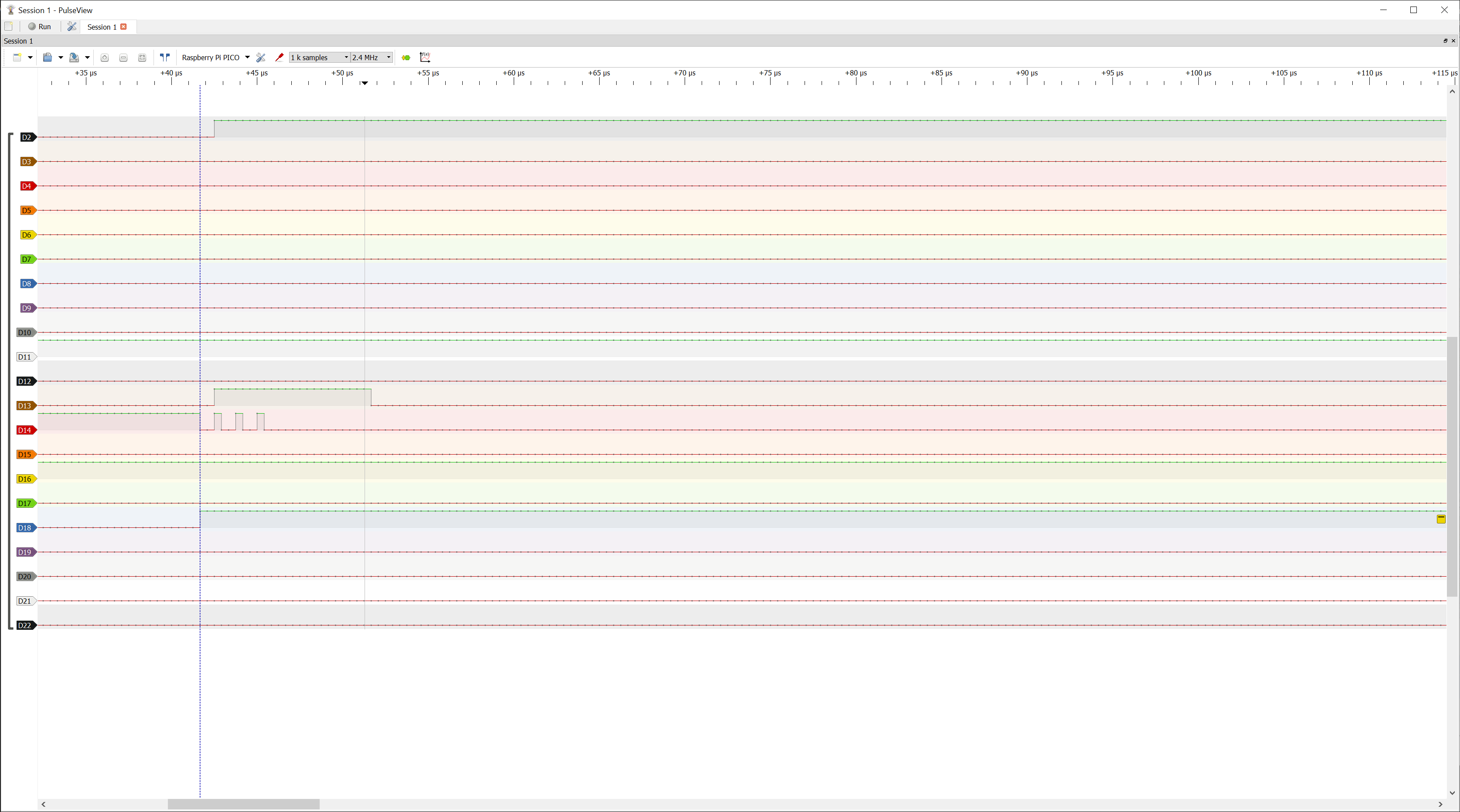
And here is what I saw at different RP2040 clocking speed.
1MHz

All good... The beginning and end of each batch is timed by the count enable pin (D14, H--> hold, L--> Count). Here you can see how the binary counting of the first pins keeps increasing during each batch as I am on purpose not resetting the counter.
5MHz

Something seems off in D13 (LE). This pin is responsible of telling the latch to latch the data. The latch saves the data at the moment when the pin goes high (with some ps delay). However, seems the pin is staying high 5 cycles longer than what it should...
10MHz

At 10MHz clock frequency the D13 pins remains in a always on state. For this reason the latch saves only the first data at the beginning of the acquisition group and keeps returning the same number as it misses the overwriting signals. This is the reason why the number I was getting were correct (I was expecting a 2 and getting a 2) but were not updated for each batch inside a single acquisition, leading to wrong data such as:
[2, 2, 2, 2, 2, 2, 2, 2, 2, 2, 2, 2, 2, 2, 2, 2, ...]
In the first batch the counter counted 2 pulses. The board saves this number in the latch, however, the latch is never re-written as its trigger pin is always high after the first batch.
I am still unsure of what was going on in this case but my first guess is that the GPIO pulldown of the RP2040 was not doing its proper job. Adding an extra pulldown on that pin immediately solved the problem and the board started working properly at all clock speeds returning correct data:
[0, 1, 0, 0, 0, 0, 0, 0, 0, 0, 0, 0, 0, 0, 0, 1, 0, 0, ... , 0, 0]
which gives a correct Poissonian distribution for each acquisition dataset 🎉🙂.
Heating
The first (or actually second, as the first was a big failure) version of the board made me notice that the MC100EP016A counter was getting “a bit” warm. My first guess was having screwed up some of the electrical connections to the IC or perhaps some of the weird PECL terminations.
It appears that, instead, this was caused by a simpler mistake, not reading the docs properly... Page 5 of the spec sheet points out the thermal resistance of the IC that is (in my opinion) pretty high considering that its typical power consumption is of the order of .
As I've chosen a LQFP package for making my life easier when soldering I should have expected a increase in temperature 🔥🔥.
Reading the specs more carefully while trying to understand which heating to expect I noticed an interesting new units to add to my (unfortunately, already extensive) collection, the lfpm. Lfpm or Linear Feet per Minute, for whomever is wondering, is a unit of airflow and (I assume) it suggests that a airflow might be needed when using the LQFP package in order to keep the IC temperature below its maximum rating of .

I monitored the temperature without airflow or heatsinks and did not measure values higher than .
However, I would strongly suggest to include at least some small heatsinks (similar to the ones that can be used on Raspberry Pi boards).